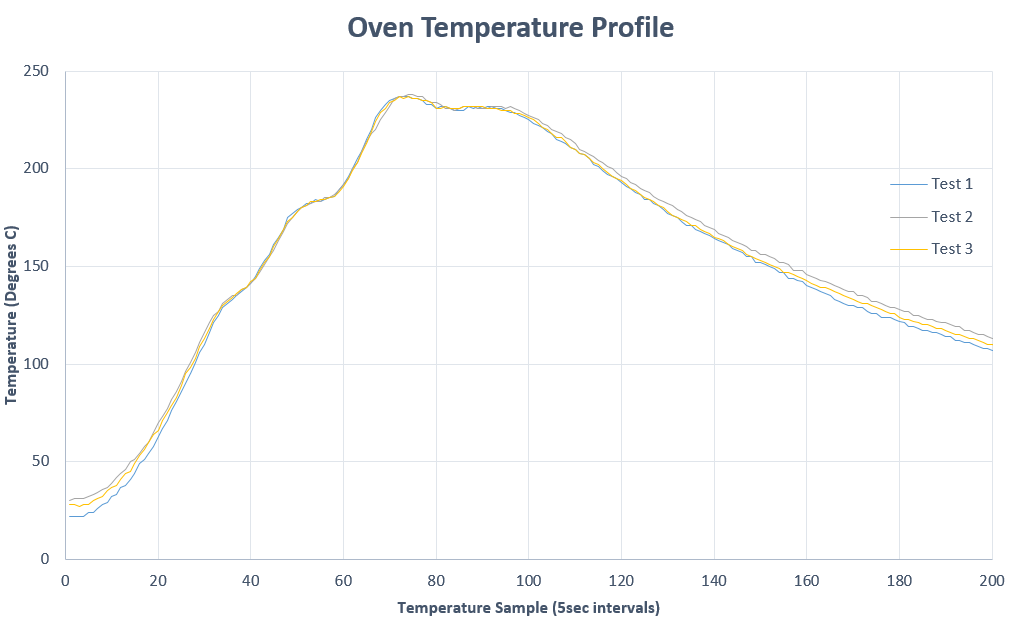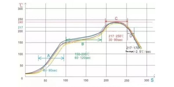


The processed board is cooling down in the last zones of the reflow oven, the solder alloy solidifies and makes the solder joints. The component that has the lowest maximum temperature allowance will define the maximum temperature. This maximum temperature must remain under the maximum allowed temperature of the components. In the third section the solder paste is melted and the process reaches its maximum temperature. The Temperature gradient is important because too quick changes of temperature can cause damage to components.ĭuring the thermal soak the flux is activated to reduce oxidation of pads and leads of components and improve wetting. The aim of the preheating stage is to accumulate heat smoothly in the board and the components. Reflow solder profiles usually have four stages, preheat, thermal soak, reflow and cooling. The solder profile is influenced by the number of layers in the PCB, the copper distribution on the board, the number and size of components. Solder profiles need to be optimised for each individual assembly job. Multiple segments help to get an optimised heat transfer and minimum temperature differences between different points on the PCBA. These are long convection ovens with many heating zones that together create a soldering cycle.Įach heating zone of the oven has a regulated temperature set to the solder profiles for the assembly process. The solder paste melts during this process and cools down again to create a good solder joint. After removing the old solder, apply a small amount of flux and then, using a soldering iron, use a small but sufficient amount of the high-temperature solder.During the Pick & Place operation, components are glued to the board by the solder paste.Ī reliable connection is made during the reflow soldering process. As already stated, profiling is a tedious process and there is nothing worse than losing a thermocouple during a run as this means having to do it over again. Otherwise, the Sn63/Pb37 will reflow underneath the adhesive. This should also be done if there are conductive adhesive used attaching the thermocouple. It is therefore mandatory that the existing solder at the interconnect be removed using solder-wick. The original lower-temperature alloy will reflow and undermine the higher-temperature solder, and the user will lose the connection of the thermocouple. As the board was likely soldered with Sn63/ Pb37, perhaps Sn10/ Pb90 should be applied, if the thermocouple will be soldered with the latter, a „mystery“ alloy would wind up, one that will not sustain the multiple thermal excursions required of the test board. Since a previously soldered assembly will be used, it is essential to remove the solder from the interconnects where the thermocouples will be attached. most vulnerable component) and other high-mass ones to assure they are seeing sufficient heat. Place other thermocouples at interconnections of heat-sensitive components (i.e. The coolest spot will likely be an interconnect of a high-mass component (a QFP, PLCC, BGA, etc.) near the center of the board. The warmest item will typically be a low mass component (a small passive) located near a corner or edge of the board. For a precise measurement of the temperatures during a reflow soldering process, the commonly used thermocouples (less than or equal to AWG 30) have a. Thermocouples will be attached at interconnections (lead-to-pad junctions) that represent the warmest and coolest points on a board. Unless there is no reflow soldering of bare boards, profiling with an unpopulated board is fruitless. Use an assembly that is populated with the same component mix as it will be passing through the oven during the actual assembly process. The reflow profiling will therefore become one of the most critical process steps in the assembly line effecting product quality. As the proposed lead-free paste reflows at a higher temperature, the maximum peak will be limited by the most sensitive components (typically at 235 to 240☌), rather than by new pastes. Regardless of which lead-free paste is used, the thermal-process window will tighten up significantly. The alloy has to be economical, and this puts a damper on indium and, possibly, large portions of bismuth. Of primary concern in soldering is that the melting temperature be below 200☌ and thus the reflow (full liquidus) temperature should be below 220☌, and even that is an uncomfortable thermal excursion for many components found on most PCB assemblies. This means coming up with a substitute for tin-lead, particularly Sn63/Pb37 and Sn62/Pb36/2Ag. The EU WEEE draft directive is a tall order which would ban lead from electrical and electronic equipment as of January 1, 2004.


 0 kommentar(er)
